0 轮廓线渲染方法 在 《RTR3》 中,作者分成了 5 种类型:
基于观察方向 $V$ 和表面法线 $N$ 。
通过观察方向和表面法线点乘结果来得到轮廓线信息。简单快速,但局限性大。
过程式几何轮廓线渲染 :法线外拓 + Cull Front
核心是两个 Pass:
第一个 Pass 只渲染背面并且让轮廓可见(比如通过顶点外扩);
第二个 Pass 正常渲染正面。快速有效,适应于大多数表面平滑的模型,但不适合立方体等平整模型。
基于图像处理 。
可以适用于任何种类的模型。但是一些深度和法线变化很小的轮廓无法检测出来,如桌子上一张纸。
基于轮廓边检测
上述方法无法控制轮廓线的风格渲染,例如水墨风格等,使用该方法可以进行风格化渲染 。缺点是实现相对复杂,会有动画连贯性问题,因为是逐帧单独提取轮廓,所以帧与帧之间会出现跳跃性。
检测一条边是否是轮廓边的方法 :检查这条边相邻的两个三角面片是否满足:$(n_0·v> 0) ≠ (n_1·v > 0)$。
$n_0$ 和 $n_1$ 表示两个相邻三角面片的法向,$v$ 是从视角到该边上任意顶点的方向。本质是检查相邻两个三角是否一个面向视角,另一个背向视角 。可以使用几何着色器实现该功能
混合上述方法 。例如,首先找到精确的轮廓线,把模型和轮廓边渲染到纹理中,再使用图像处理识别轮廓线,并在图像空间进行风格化渲染。
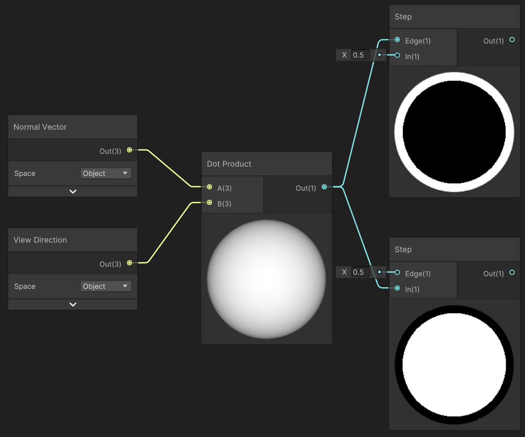
1 基于观察方向和表面法线 通过观察方向 $V$ 和表面法线 $N$ 点乘结果来得到轮廓线信息。简单快速,但局限性大。
Edge=0.5 时
1
2
float NdotV = dot(N,V);float color = step(_Edge, NdotV);
2 模板测试描边 模板测试选项设置思路很灵活,我这里只写了一种设置方法。
模板缓冲区设置 1 2 3 4 5 6 7 8 Stencil { Ref 0 Comp Equal Pass IncrSat Fail Keep ZFail keep }
第一个 pass :渲染前屏幕上所有像素的 stencil 值都是默认值 0,在该 pass 的 fragment shader 结束后,所有进行了渲染的像素都通过了 Ref 0 和 Comp Equal 的测试,并执行 Pass IncrSat 将 stencil 值加 1。第二个 Pass :
把每个顶点沿法线方向外扩。方案如下:
在模型/世界空间外扩 :远近描边的粗细不同 。造成这个问题的原因:在裁剪之前做的变换,最后长度都会符合世界空间下因为相机透视造成的近大远小的效果。实际上还要考虑许多因素,详情看矫正篇。【矫正】 [[#描边粗细解决方案]]
随后设置法线的 z 分量,对其归一化后再将顶点沿其方向扩张,得到扩张后的顶点坐标。对法线的处理是为了尽可能避免背面扩张后的顶点挡住正面的面片。
最后 ,我们把顶点从视角空间变换到裁剪空间。进行同样的 stencil 测试,上一个 pass 渲染过的像素 stencil 值已经变为 1,无法通过 Ref 0+Comp Equal 测试,那么现在只会在放大后的既是 stencil 值仍然为 0 的边缘区域进行渲染。
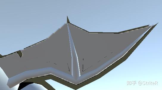
缺陷:两个模型重叠部分没有描边,无解
fold 1 2 3 4 5 6 7 8 9 10 11 12 13 14 15 16 17 18 19 20 21 22 23 24 25 26 27 28 29 30 31 32 33 34 35 36 37 38 39 40 41 42 43 44 45 46 47 48 49 50 51 52 53 54 55 56 57 58 59 60 61 62 63 64 65 66 67 68 69 70 71 72 73 74 75 76 77 78 79 80 81 82 83 84 85 86 87 88 89 90 91 92 93 94 95 96 97 98 99 100 101 102 103 104 105 106 107 108 109 110 111 112 113 114 115 116 Shader "Custom/StencilTestOutline" { Properties { _MainTex ("MainTex" , 2 D) = "white" {} [HDR]_EdgeColor("EdgeColor" , Color) = (0 ,0 ,0 ,0 ) _EdgeScale("EdgeScale" , Range(0 , 1 )) = 0.01 } SubShader { Tags { "RenderPipeline" = "UniversalPipeline" "RenderType" ="Opaque" } Stencil { Ref 0 Comp Equal Pass IncrSat Fail Keep ZFail keep } HLSLINCLUDE #include "Packages/com.unity.render-pipelines.universal/ShaderLibrary/Core.hlsl" CBUFFER_START(UnityPerMaterial) float4 _MainTex_ST; float4 _EdgeColor; float _EdgeScale; float _OutlineSpace; CBUFFER_END TEXTURE2D (_MainTex) ; SAMPLER(sampler_MainTex); struct Attributes { float4 positionOS : POSITION; float2 uv : TEXCOORD0; float3 normalOS: NORMAL; }; struct Varyings { float4 positionCS : SV_POSITION; float2 uv : TEXCOORD0; float3 normal : TEXCOORD1; }; ENDHLSL Pass { Name "Shading" Tags { "LightMode" = "SRPDefaultUnlit" } HLSLPROGRAM #pragma vertex vert #pragma fragment frag Varyings vert(Attributes i) { Varyings o = (Varyings)0 ; o.positionCS = TransformObjectToHClip(i.positionOS.xyz); o.uv = i.uv.xy * _MainTex_ST.xy + _MainTex_ST.zw; return o; } float4 frag (Varyings i) : SV_Target { float4 MainTex = SAMPLE_TEXTURE2D(_MainTex, sampler_MainTex, i.uv); float4 finalColor = MainTex; return finalColor; } ENDHLSL } Pass { Name "Outline" Tags { "LightMode" = "UniversalForward" } HLSLPROGRAM #pragma vertex vert #pragma fragment frag Varyings vert(Attributes i) { Varyings o = (Varyings)0 ; o.uv = TRANSFORM_TEX(i.uv, _MainTex); i.positionOS.xyz += normalize(i.normalOS) * _EdgeScale; o.positionCS = TransformObjectToHClip(i.positionOS.xyz); return o; } float4 frag (Varyings i) : SV_Target { return _EdgeColor; } ENDHLSL } } }
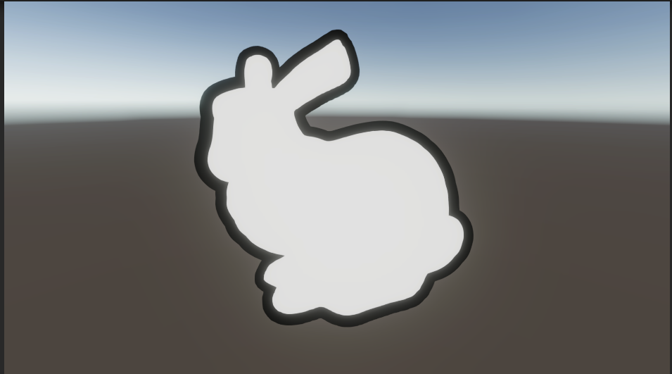
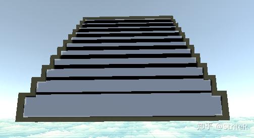
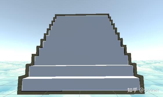
3 过程式几何轮廓线渲染 其实就是把前面的模板测试换成了剔除操作 。快速有效,适应于大多数表面平滑的模型,但不适合立方体 等平整模型。
核心是两个 Pass:
第一个 Pass 剔除正面,只渲染背面。进行顶点外扩。
第二个 Pass 正常渲染正面。
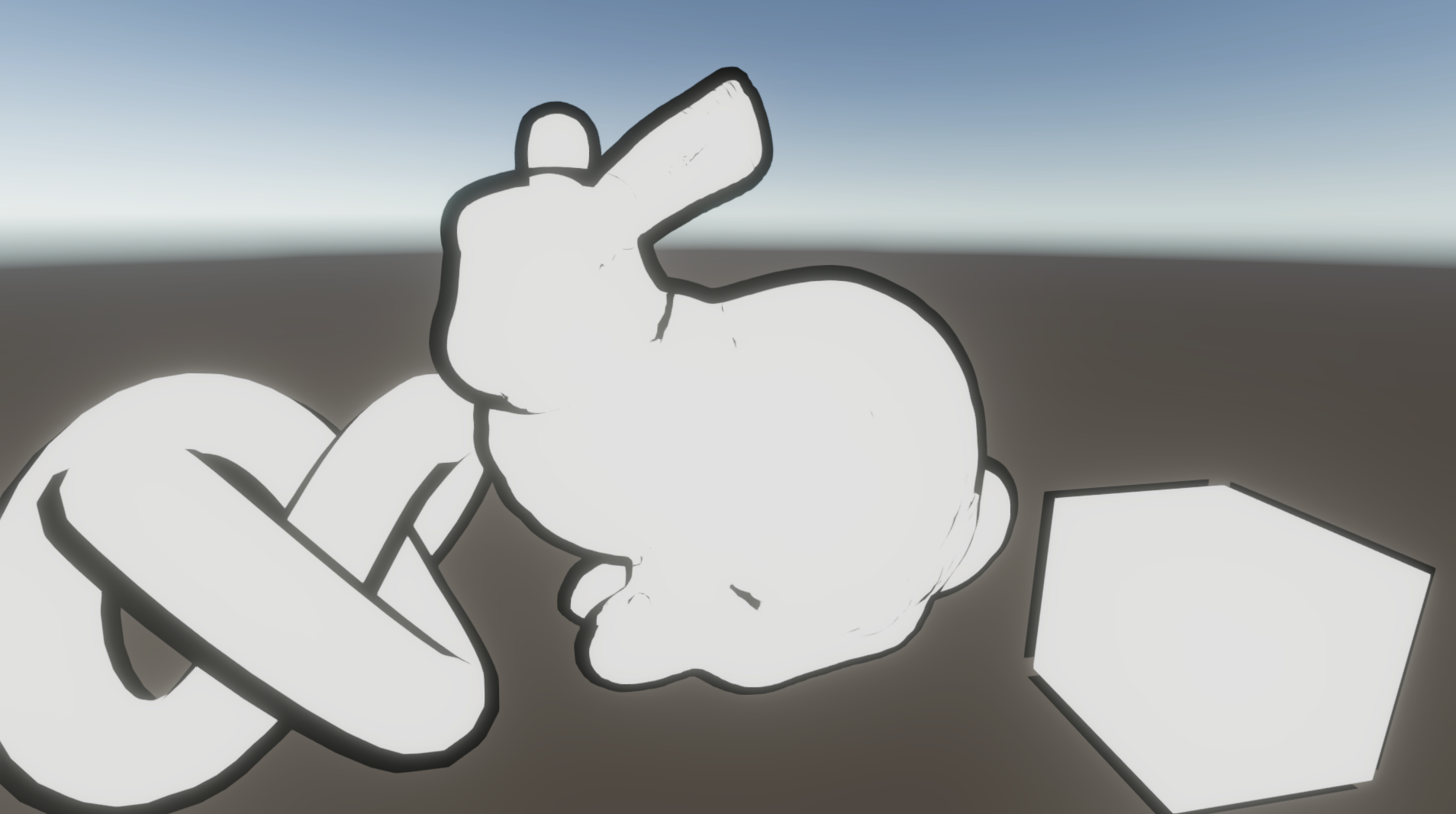
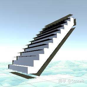
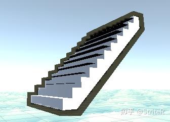
如果直接使用顶点法线进行顶点外扩,对于一些内凹的模型,就可能发生背面面片遮挡正面面片的情况。 为了尽可能防止出现这样的情况,在扩张背面顶点之前,我们首先对顶点法线的 z 分量(即 normal 值,TBN 的N)进行处理,使它们等于一个定值,然后把法线归一化后再对顶点进行扩张。 这样的好处在于,扩展后的背面更加扁平化,从而降低了遮挡正面面片的可能性。
1 2 normal.z = -0.5 ; normal = normalize(normal);
fold 1 2 3 4 5 6 7 8 9 10 11 12 13 14 15 16 17 18 19 20 21 22 23 24 25 26 27 28 29 30 31 32 33 34 35 36 37 38 39 40 41 42 43 44 45 46 47 48 49 50 51 52 53 54 55 56 57 58 59 60 61 62 63 64 65 66 67 68 69 70 71 72 73 74 75 76 77 78 79 80 81 82 83 84 85 86 87 88 89 90 91 92 93 94 95 96 97 98 99 100 101 102 103 104 105 106 107 108 Shader "Custom/ProceduralGeometryOutline" { Properties { _MainTex ("MainTex" , 2 D) = "white" {} [HDR]_EdgeColor("EdgeColor" , Color) = (0 ,0 ,0 ,0 ) _EdgeScale("EdgeScale" , Range(0 , 1 )) = 0.01 _NormalZ("NormalZ" , Range(-1 , 1 )) = 0.5 } SubShader { Tags { "RenderPipeline" = "UniversalPipeline" "RenderType" ="Opaque" } HLSLINCLUDE #include "Packages/com.unity.render-pipelines.universal/ShaderLibrary/Core.hlsl" CBUFFER_START(UnityPerMaterial) float4 _MainTex_ST; float4 _EdgeColor; float _EdgeScale; float _OutlineSpace; float _NormalZ; CBUFFER_END TEXTURE2D (_MainTex) ; SAMPLER(sampler_MainTex); struct Attributes { float4 positionOS : POSITION; float2 uv : TEXCOORD0; float3 normalOS: NORMAL; }; struct Varyings { float4 positionCS : SV_POSITION; float2 uv : TEXCOORD0; float3 normal : TEXCOORD1; }; ENDHLSL Pass { Name "Outline" Tags { "LightMode" = "SRPDefaultUnlit" } Cull Front HLSLPROGRAM #pragma vertex vert #pragma fragment frag Varyings vert(Attributes i) { Varyings o = (Varyings)0 ; o.uv = TRANSFORM_TEX(i.uv, _MainTex); i.normalOS.z =_NormalZ; i.positionOS.xyz += normalize(i.normalOS) * _EdgeScale; o.positionCS = TransformObjectToHClip(i.positionOS.xyz); return o; } float4 frag (Varyings i) : SV_Target { return _EdgeColor; } ENDHLSL } Pass { Name "Shading" Tags { "LightMode" = "UniversalForward" } HLSLPROGRAM #pragma vertex vert #pragma fragment frag Varyings vert(Attributes i) { Varyings o = (Varyings)0 ; o.positionCS = TransformObjectToHClip(i.positionOS.xyz); o.uv = i.uv.xy * _MainTex_ST.xy + _MainTex_ST.zw; return o; } float4 frag (Varyings i) : SV_Target { float4 MainTex = SAMPLE_TEXTURE2D(_MainTex, sampler_MainTex, i.uv); float4 finalColor = MainTex; return finalColor; } ENDHLSL } } }
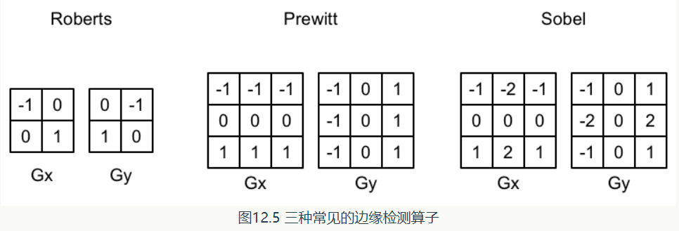
4 边缘检测 后处理边缘检测 如果相邻像素之间存在明显差别的颜色、亮度、纹理等属性,我们就会认为它门之间应该有一条边界。这张相邻像素之间的差值可以用梯度(gradient) 表示。边缘处的梯度绝对值比较大。
边缘检测的原理其实就是用一个特定的卷积核去对一张图像卷积,得到梯度值,再根据梯度值的大小去判断是否为边界。
注意这些算子不满足线性可分,不能使用高斯模糊使用的优化方法
3 种常见的边缘检测算子如图所示,它们都包含了两个方向的卷积核 $G_x$ $G_y$,分别用于检测水平方向和竖直方向上的边缘信息 。在进行边缘检测时,我们需要对每个像素分别进行一次卷积计算,得到两个方向上的梯度值 $g_x$, 和 $g_y$,, 而整体的梯度可按下面的公式计算而得:由于上述计算包含了开根号操作,出于性能的考虑,我们有时会使用绝对值操作来代替开根号操作:
Sobel 算子描边描边 1 2 3 4 5 6 7 8 9 10 11 12 13 14 15 16 17 18 19 20 21 22 23 24 25 26 27 28 29 30 31 32 33 34 35 36 37 float luminance (float3 color ){ return 0.2125 * color.r + 0.7154 * color.g + 0.0721 * color.b; } float Sobel (Varyings i ){ const float GX[9 ] = { -1 , -2 , -1 , 0 , 0 , 0 , 1 , 2 , 1 }; const float GY[9 ] = { -1 , 0 , 1 , -2 , 0 , 2 , -1 , 0 , 1 }; float texColor; float gx, gy; for (int it = 0 ; it < 9 ; it++) { texColor = luminance(SAMPLE_TEXTURE2D_X(_BlitTexture, sampler_BlitTexture, i.uv[it]).rgb); gx += texColor * GX[it]; gy += texColor * GY[it]; } float G = abs(gx) + abs(gy); return G; }
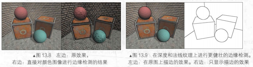
优化:基于深度法线纹理 上面方法的缺陷 :这种方法下如果两个物体颜色等信息接近,就检测不出来了。另外直接利用颜色信息进行边缘检测的方法会产生很多我们不希望得到的描边,如模型的纹理和阴影等位置也被描边。优化 :创建适用于所有几何体和颜色的有效轮廓着色器的解决方案是考虑颜色、法线向量和/或深度不连续性 。在深度法线纹理 上进行边缘检测,这些图像不会受纹理和光照影响,而仅仅保存了当前渲染物体的模型信息。
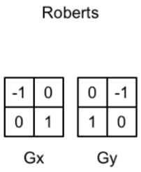
使用 Robert 算子:
1 2 3 4 5 6 7 8 9 10 11 12 13 14 15 16 17 18 19 20 21 22 23 24 25 26 27 28 29 30 31 32 33 34 35 36 37 38 39 40 41 42 43 44 45 46 47 float CheckSame (float4 center, float4 sample) { float2 centerNormal = center.xy; float centerDepth = center.z; float2 sampleNormal = sample.xy; float sampleDepth = sample.z; float2 diffNormal = abs (centerNormal-sampleNormal)*_SensitivityNormals; int isSameNormal = (diffNormal.x+diffNormal.y) < 0.1 ; float diffDepth = abs (centerDepth-sampleDepth)*_SensitivityDepth; int isSameDepth = diffDepth < 0.1 ; return isSameNormal*isSameDepth?1.0 :0.0 ; } float4 frag (Varyings i) : SV_Target { float4 sample1; float4 sample2; float4 sample3; float4 sample4; sample1.xy = SAMPLE_TEXTURE2D_X(_CameraNormalsTexture, sampler_CameraNormalsTexture, i.uv[1 ]).rg; sample1.z = Linear01Depth(SAMPLE_TEXTURE2D_X(_CameraDepthTexture, sampler_CameraDepthTexture, i.uv[1 ]).r,_ZBufferParams); sample2.xy = SAMPLE_TEXTURE2D_X(_CameraNormalsTexture, sampler_CameraNormalsTexture, i.uv[2 ]).rg; sample2.z = Linear01Depth(SAMPLE_TEXTURE2D_X(_CameraDepthTexture, sampler_CameraDepthTexture, i.uv[2 ]).r,_ZBufferParams); sample3.xy = SAMPLE_TEXTURE2D_X(_CameraNormalsTexture, sampler_CameraNormalsTexture, i.uv[3 ]).rg; sample3.z = Linear01Depth(SAMPLE_TEXTURE2D_X(_CameraDepthTexture, sampler_CameraDepthTexture, i.uv[3 ]).r,_ZBufferParams); sample4.xy = SAMPLE_TEXTURE2D_X(_CameraNormalsTexture, sampler_CameraNormalsTexture, i.uv[4 ]).rg; sample4.z = Linear01Depth(SAMPLE_TEXTURE2D_X(_CameraDepthTexture, sampler_CameraDepthTexture, i.uv[4 ]).r,_ZBufferParams); float edge = 1.0 ; edge *= CheckSame(sample1, sample2); edge *= CheckSame(sample3, sample4); float4 withEdgeColor = lerp(_EdgeColor,SAMPLE_TEXTURE2D(_BlitTexture, sampler_BlitTexture, i.uv[0 ]),edge); float4 onlyEdgeColor = lerp(_EdgeColor, _BackgroundColor, edge); return lerp(withEdgeColor, onlyEdgeColor, _EdgesOnly); }
2D 边缘检测 采样像素周围的点,如果有一个点透明度为 0,就说明是边缘
2D 常用。也可用于 2D 的边缘光。
1 2 3 4 5 6 7 8 9 10 11 12 13 14 15 16 17 18 19 20 float4 UnlitFragment (Varyings i) : SV_Target { float4 mainTex = i.color * SAMPLE_TEXTURE2D(_MainTex, sampler_MainTex, i.uv); float2 up_uv = i.uv + float2(0 , 1 ) * _LineWidth * 1 / 10 * _MainTex_ST.xy; float2 down_uv = i.uv + float2(0 , -1 ) * _LineWidth * 1 / 10 * _MainTex_ST.xy; float2 left_uv = i.uv + float2(-1 , 0 ) * _LineWidth * 1 / 10 * _MainTex_ST.xy; float2 right_uv = i.uv + float2(1 , 0 ) * _LineWidth * 1 / 10 * _MainTex_ST.xy; float4 up = SAMPLE_TEXTURE2D(_MainTex, sampler_MainTex, up_uv); float4 down = SAMPLE_TEXTURE2D(_MainTex, sampler_MainTex, down_uv); float4 left = SAMPLE_TEXTURE2D(_MainTex, sampler_MainTex, left_uv); float4 right = SAMPLE_TEXTURE2D(_MainTex, sampler_MainTex, right_uv); float w = up.a * down.a * left.a * right.a; if (w == 0 ) { mainTex.rgb = lerp(_LineColor * _Intensity, mainTex.rgb, w); } return mainTex; }
5 SDF 描边(鸽)
关于 SDF 我在之前的文章中有过分析:
何博航:Signed Distance Field 与 Multi-channel signed distance field
之前也在 UE4 中实现过,但是还是刚接触 Unity Shader 没几天,对 shaderlab 还不熟悉。这里主要参考了前辈的文章,在其基础上稍作修改:
拳四郎:Signed Distance Field
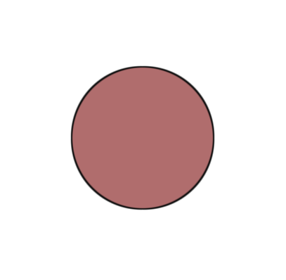
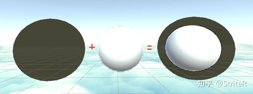
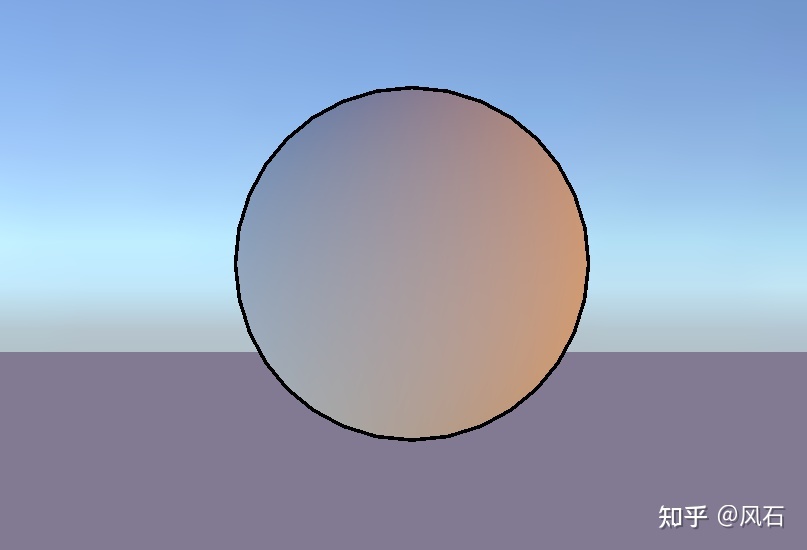
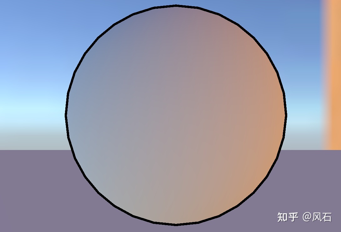
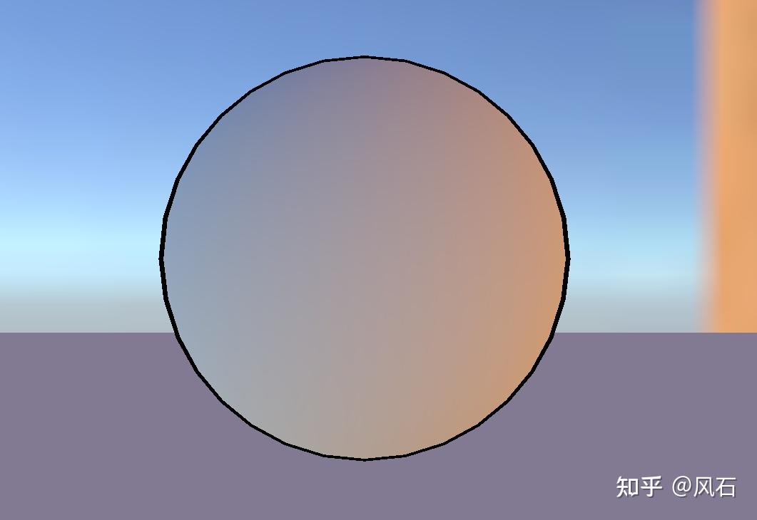
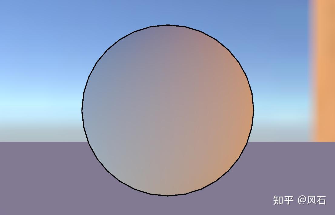
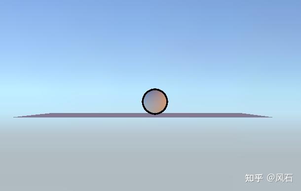
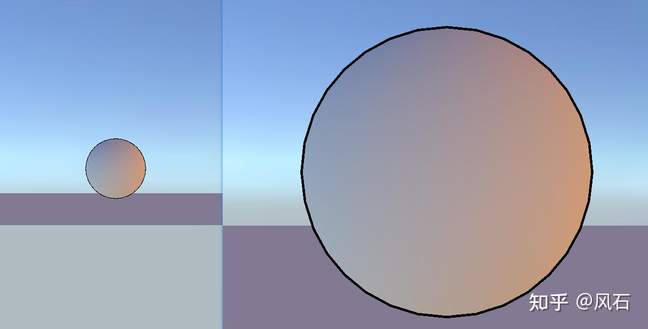
描边结果:
原理其实很简单,这里的圆是在 shader 中根据 SDF 值绘制的。SDF 值在边界处接近 0,于是我们就通过 SDF 的 fwidth 值与当前像素的 SDF 值去判断,因为 fwidth 为相邻像素的 SDF 差值和,那么必然很小。所以判断的结果用于 lerp,就可以检测哪里的 SDF 值接近 0,亦即检测到轮廓。而 aa 也是简单地用 smoothstep 处理就好。
给出完整代码:
1 2 3 4 5 6 7 8 9 10 11 12 13 14 15 16 17 18 19 20 21 22 23 24 25 26 27 28 29 30 31 32 33 34 35 36 37 38 39 40 41 42 43 44 45 46 47 48 49 50 51 52 53 54 55 56 57 58 59 60 61 62 63 64 Shader "OutlineShader/sdfOutline" { Properties { _Color ("Color", Color) = (1, 1, 1, 1) _BackgroundColor ("BackgroundColor", Color) = (0, 0, 0, 1) } SubShader { Pass { CGPROGRAM #pragma vertex vert #pragma fragment frag #include "UnityCG. cginc" float sdfCircle(float2 coord, float2 center, float radius) { float2 offset = coord - center; return sqrt((offset.x * offset.x) + (offset.y * offset.y)) - radius; } float4 render(float d, float3 color, float stroke) { float anti = fwidth(d) * 1.0; float4 colorLayer = float4(color, 1.0 - smoothstep(-anti, anti, d)); bool flag = step(0.000001, stroke); float4 strokeLayer = float4(float3(0.05, 0.05, 0.05), 1.0 - smoothstep(-anti, anti, d - stroke)); return float4(lerp(strokeLayer.rgb, colorLayer.rgb, colorLayer.a), strokeLayer.a) * flag + colorLayer * (1 - flag); } struct appdata { float4 vertex : POSITION; }; struct v2f { float4 pos : SV_POSITION; float4 screenPos : TEXCOORD0; }; fixed4 _Color; fixed4 _BackgroundColor; v2f vert (appdata v) { v2f o; o.pos = UnityObjectToClipPos (v.vertex); o.screenPos = ComputeScreenPos(o.pos); return o; } fixed4 frag(v2f i) : SV_Target { float2 pixelPos = (i.screenPos.xy / i.screenPos.w) * _ScreenParams.xy; float a = sdfCircle(pixelPos, float2(0.5, 0.5) * _ScreenParams.xy, 100); float4 layer1 = render(a, _Color, fwidth(a) * 2.0); return lerp(_BackgroundColor, layer1, layer1.a); } ENDCG } } }
6 基于轮廓边检测的方法(鸽) 再来回顾一下之前所述的原理:
检查这条边相邻的两个三角面片是否满足:(n0·v> 0) ≠ (n1·v > 0)。这里 n0 和 n1 分别表示两个相邻三角面片的法向,v 是从视角到该边上任意顶点的方向。本质是检查相邻两个三角是否一个面向视角,另一个背向视角。
于是这里我想到用几何着色器去做,但是不知道怎么获得相邻的三角面片,在 OpenGL 中有 GL_LINES_ADJACENCY 去得到线段以及相邻顶点,就正好四个顶点两个相邻面片,从而可以去处理。但是 Unity Shader 中我没有找到怎么做。但是在谷歌中搜索出了一个解决方法: https://forum.unity.com/threads/does-unity-support-triangleadj-in-geometry-shaders.930306/
先给他的链接,还没来得及细看:
https://github.com/Milun/unity-solidwire-shader/blob/master/Assets/Shaders/SolidWire.shader
(物体空间外拓,视角空间外拓,裁剪空间外拓)
1 2 3 4 5 6 7 8 9 10 11 12 13 14 15 16 17 18 19 20 21 22 23 24 25 26 27 28 29 30 31 32 33 34 35 36 37 38 39 40 41 42 43 44 45 46 47 48 49 50 51 52 53 54 55 56 57 58 59 60 61 62 63 64 65 66 67 68 69 70 71 72 73 74 75 76 77 78 79 80 81 82 83 84 85 86 87 88 89 90 91 92 93 94 95 96 97 98 99 100 101 102 103 104 105 106 107 108 109 110 111 112 113 114 115 116 117 118 119 120 121 122 123 Shader "Unlit/019" { Properties { _MainTex ("Texture", 2D) = "white" {} _Diffuse ("漫反射", Color) = (1,1,1,1) _Outline ("外廓粗细", Range(0,0.05)) = 0.02 _OutlineColor ("外廓颜色", Color) = (0,0,0,0) } SubShader { Tags { "RenderType"="Opaque" } LOD 100 Pass { //定义Pass名,用于重复使用该Pass Name "Outline" //渲染前面 Cull Front CGPROGRAM #pragma vertex vert #pragma fragment frag #include "UnityCG.cginc" float _Outline; fixed4 _OutlineColor; struct v2f { float4 vertex :SV_POSITION; }; v2f vert(appdata_base v) { v2f o; //描边=顶点在法线上偏移 * 颜色 //物体空间法线外拓 //v.vertex.xyz += v.normal * _Outline; //o.vertex = UnityObjectToClipPos(v.vertex); //视角空间法线外拓 //float4 pos = mul(UNITY_MATRIX_V,mul(unity_ObjectToWorld,v.vertex)); //float3 normal = normalize (mul((float3x3)UNITY_MATRIX_IT_MV,v.normal)); //pos = pos + float4(normal,0) * _Outline; //o.vertex = mul(UNITY_MATRIX_P,pos); //裁剪空间法线外拓 o.vertex = UnityObjectToClipPos(v.vertex); float3 normal = normalize (mul((float3x3)UNITY_MATRIX_IT_MV,v.normal)); float2 viewNoraml = TransformViewToProjection(normal.xy); o.vertex.xy += viewNoraml * _Outline; return o; } float4 frag(v2f i):SV_Target { return _OutlineColor; } ENDCG } Pass { CGPROGRAM #pragma vertex vert #pragma fragment frag #include "UnityCG.cginc" //引入光照 #include "Lighting.cginc" struct v2f { float2 uv : TEXCOORD0; float4 vertex : SV_POSITION; fixed3 worldNormal : TEXCOORD1; float3 worldPos : TEXCOORD2; }; sampler2D _MainTex; float4 _MainTex_ST; float4 _Diffuse; v2f vert (appdata_base v) { v2f o; //顶点位置 o.vertex = UnityObjectToClipPos(v.vertex); //法线方向 o.worldNormal = UnityObjectToWorldNormal(v.normal); //世界坐标 o.worldPos = mul(unity_ObjectToWorld,v.vertex); //纹理坐标缩放偏移 o.uv = TRANSFORM_TEX(v.texcoord, _MainTex); return o; } fixed4 frag (v2f i) : SV_Target { // 纹理采样 fixed4 albedo = tex2D(_MainTex, i.uv); //光源方向 fixed3 worldLightDir = UnityWorldSpaceLightDir (i.worldPos); //漫反射光=入射光线强度*纹素值*材质的漫反射系数* 映射值为正数(表面法线方向 · 光源方向) fixed3 diffuse = _LightColor0.rgb * albedo * _Diffuse.rgb * (dot(worldLightDir,i.worldNormal)*0.5+0.5); //环境光 fixed3 ambient = UNITY_LIGHTMODEL_AMBIENT.xyz; fixed3 color = ambient + diffuse; return fixed4(color,1); } ENDCG } } }
法线外拓总结 法线外拓 + 深度测试 Always(存在:模型自身会穿透自身和物体将会永远再最前面问题,一般不使用这种方案)法线不是连续的时候,描边就会中断的问题
计算法线,最基础方案
1 2 3 4 5 6 7 v2f vert (appdata_base v) v2f o; v.vertex.xyz += v.normal * _OutlineWidth; o.vertex = UnityObjectToClipPos (v.vertex); return o; }
无论相机距离物体多远或者观察视角的变化,都让描边的宽度保持等比例的近似方法解决
1 2 3 4 5 6 v2f vert (appdata v) o.vertex = UnityObjectToClipPos (v.vertex); float3 clipNormal = mul ((float3x3) UNITY_MATRIX_VP, mul ((float3x3) UNITY_MATRIX_M, v.normal)); o.vertex.xy += normalize (clipNormal).xy * _OutlineWidth; }
法线外拓 通常做卡通以及二次元渲染的时候接触得较早的就是描边需求, 而描边需求在大多数情况下都会通过两种方法实现:**
全屏后处理,
法线外拓,
不过由于全屏后处理较难应付复杂的逐单位需求. 所以在调整一段时间的法线外拓后, 将自己的思考过程以本文章的形式记录下来. GitHub - striter/Unity3D-ToolChain_StriteR
MenuItem 工作流: WorkFlow/Art/Mesh Smooth Normal Generator
编辑器脚本: EWSmoothNormalGenerator. cs
Shader 代码: Outline. shader
法线外拓原理 在原始模型的基础上通过第二个渲染生成一个更大的模型并叠加.
A 的做法则是在 vertex 阶段朝着发现位置做顶点位置偏移, 一份基础法线外拓 shader 就做好了.
1 2 3 4 5 6 7 8 9 10 11 12 13 14 15 16 17 18 19 20 21 22 23 struct a2v { half3 positionOS : POSITION; half3 normalOS:NORMAL; }; struct v2f { float4 positionCS:SV_POSITION; }; v2f vert(a2v v) { v2f o; half3 positionOS=v.positionOS; half3 normalOS=normalize(v.normalOS); positionOS+=normalOS*_OutlineWidth; o.positionCS=TransformObjectToHClip(positionOS); } float4 frag(v2f i) { return _OutlineColor; }
通常叠加的方式有好几种:
Multi Pass Shader (URP 需要特殊处理)
单个 MeshRender 挂多个 Material (模型无 SubMesh 的情况)
两个 MeshRenderer 同步 Transform
与使用第二种方式原模型叠加后的结果
平滑法线 在上文的基础下测试后其实可以发现, 在遇到法线断裂 (多套光照光滑组) 的情况下, 描边的效果将会有较大的瑕疵.
问题的原因在于法线不连续. 解决方法则是生成一套连续的法线数据供描边采样.
通过 Unity 内置的 Mesh class, 可以获取原始模型的数据并制作与储存成新的 asset 资源.
平滑法线的生成流程:
对于每个顶点位置 (position), 收集该坐标相关的所有相同位置顶点 (vertex) 的法线数据.
将相关的法线数据相加并归一化后再赋回原始的所有顶点.
1 2 3 4 5 6 7 8 9 10 11 12 13 14 15 16 17 18 19 public static Vector3[] GenerateSmoothNormals(Mesh _srcMesh) { Vector3[] verticies = _srcMesh.vertices; Vector3[] normals = _srcMesh.normals; Vector3[] smoothNormals = normals.DeepCopy(); var groups = verticies.Select((vertex, index) => new KeyValuePair<Vector3, int>(vertex, index)).GroupBy(pair => pair.Key); foreach (var group in groups) { if (group.Count() == 1) continue; Vector3 smoothNormal = Vector3.zero; foreach (var index in group) smoothNormal += normals[index.Value]; smoothNormal = smoothNormal.normalized; foreach (var index in group) smoothNormals[index.Value] = smoothNormal; } return smoothNormals; }
将生成的法线数据赋值到 Tangents 数组 内, 即可采样描边.
1 normalOS=normalize(v.tangentOS.xyz);
赋值到 tangents 的原因是: 对于骨骼动画模型 (SkinnedMeshRenderer), Unity 黑盒在计算动画时, 将 normal 跟 nangent 一并计算成最终数据 (原本是是要 tangent 用于做法线贴图).
使用重新生成的法线数据 (可选)
在多数卡通游戏制作流程中, 模型的光照组由于各种调整失去了连续性, 以在这种情况下使用调整后的 normal 数据并不能很好的生成描边数据.
通过顶点以及 UV 重新生成三角面并获取法线, 可以生成垂直于面片的法线会有部分改善.
1 2 3 4 5 6 7 8 9 10 11 12 13 14 15 16 17 18 19 20 21 22 23 24 25 26 27 28 29 30 31 32 33 34 35 36 37 38 39 40 41 42 43 44 45 46 47 48 49 50 51 52 53 54 55 56 57 58 59 60 61 62 static Vector3[]RenegerateNormals(int[] _indices, Vector3[] _verticies) { Vector3[] normals = new Vector3[_verticies.Length]; GTrianglePolygon[] polygons = GetPolygons(_indices); foreach(var polygon in polygons) { GTriangle triangle = new GTriangle(polygon.GetVertices(_verticies)); Vector3 normal = triangle.normal; foreach (var index in polygon) normals[index] += normal; } normals=normals.Select(normal => normal.normalized).ToArray(); return normals; } static GTrianglePolygon[] GetPolygons(int[] _indices) { GTrianglePolygon[] polygons = new GTrianglePolygon[_indices.Length / 3]; for (int i = 0; i < polygons.Length; i++) { int startIndex = i * 3; int triangle0 = _indices[startIndex]; int triangle1 = _indices[startIndex + 1]; int triangle2 = _indices[startIndex + 2]; polygons[i] = new GTrianglePolygon(triangle0, triangle1, triangle2); } return polygons; } public struct GTrianglePolygon { public int index0; public int index1; public int index2; public GTrianglePolygon(int _index0, int _index1, int _index2) { index0 = _index0; index1 = _index1; index2 = _index2; } public (T v0, T v1, T v2) GetVertices<T>(IList<T> _vertices) => (_vertices[index0], _vertices[index1],_vertices[index2]); } public struct GTriangle { public Triangle<Vector3> triangle; public Vector3 normal; public Vector3 uOffset; public Vector3 vOffset; public GTriangle((Vector3 v0,Vector3 v1,Vector3 v2) _tuple) : this(_tuple.v0,_tuple.v1,_tuple.v2) { } public GTriangle(Vector3 _vertex0, Vector3 _vertex1, Vector3 _vertex2) { triangle = new Triangle<Vector3>(_vertex0, _vertex1, _vertex2); uOffset = _vertex1-_vertex0; vOffset = _vertex2-_vertex0; normal= Vector3.Cross(uOffset,vOffset); } }
更平滑的数据 上述方法存在瑕疵 (法线连续性不足), 若对描边有更细致的精度需求, 最好的方法则是通过建模软件修改法线方向, 也可以在生成的 Mesh 基础上对模型进行调整, 例如在工作流内有一份内置的模型编辑器 (WorkFlow/Art/MeshEditor)(操作未优化, 比较反人类), 亦或者将 Mesh 导出 (通过 FBXExporter) 后编辑.
UV 储存描边数据 由于占用了 Tangent 的数据, 若遇到蒙皮数据 , 法线贴图 与平滑描边 共存的情况, 在原始的则需要特殊处理, 后续在网上翻阅资料后发现可以参考法线贴图的做法, 将切线空间数据存储到 UV0-9 的信息里, 通过 TBN 矩阵反乘处理即可用于采样.
数据构建 (C#):
1 2 3 4 5 6 7 8 9 10 11 12 13 14 15 16 17 18 19 20 21 22 23 24 25 26 27 28 29 30 31 32 33 34 35 public static Vector3[] GenerateSmoothNormals(Mesh _srcMesh, bool _convertToTangentSpace) { Vector3[] verticies = _srcMesh.vertices; var groups = verticies.Select((vertex, index) => new KeyValuePair<Vector3, int>(vertex, index)).GroupBy(pair => pair.Key); Vector3[] normals = RenegerateNormals(_srcMesh.triangles,verticies); Vector3[] smoothNormals = normals.DeepCopy(); foreach (var group in groups) { if (group.Count() == 1) continue; Vector3 smoothNormal = Vector3.zero; foreach (var index in group) smoothNormal += normals[index.Value]; smoothNormal = smoothNormal.normalized; foreach (var index in group) smoothNormals[index.Value] = smoothNormal; } //通过构建TBN矩阵,将平滑法线数据转到切线空间内 if (_convertToTangentSpace) { Vector4[] tangents = _srcMesh.tangents; for (int i = 0; i < smoothNormals.Length; i++) { Vector3 tangent = tangents[i].ToVector3().normalized; Vector3 normal = normals[i].normalized; Vector3 biNormal = Vector3.Cross(normal, tangent).normalized * tangents[i].w; Matrix3x3 tbnMatrix = Matrix3x3.identity; tbnMatrix.SetRow(0, tangent); tbnMatrix.SetRow(1, biNormal); tbnMatrix.SetRow(2, normal); smoothNormals[i] = tbnMatrix * smoothNormals[i].normalized; } } return smoothNormals; }
数据采样 (Shader Vertex):
1 2 3 4 5 6 7 8 9 10 float3 normalOS=0; #if _NORMALSAMPLE_UV1 normalOS=normalize(v.uv1); #elif _NORMALSAMPLE_UV2 normalOS=normalize(v.uv2); //34567... #endif float3x3 TBNOS=float3x3(v.tangentOS.xyz,cross(v.normalOS,v.tangentOS.xyz)*v.tangentOS.w,v.normalOS); normalOS=mul(normalOS,TBNOS);
内描边剔除 通常内描边可以呈现物体的几何形状, 但是在某些情况下 (粗描边, 几何嵌套程度过高), 内描边会带来明显的瑕疵感.
解决方案通常是通过将法线外拓的内描边遮盖后, 再通过贴图采样的内描边解决, 而 Stencil 则是解决法线外拓造成的内描边方式之一.
通过在渲染上层模型时赋值指定的 Stencil, 在渲染描边时通过 Stencil 比较丢弃多余的像素.
1 2 3 4 5 6 7 8 9 10 11 12 13 14 15 //模型Shader的Stencil参考 Stencil { Ref 1 Comp Always Pass Replace } //描边Shader的Stencil参考 Stencil { Ref 1 Comp NotEqual Pass Keep }
自适应描边 由于法线拓展在模型空间 , 将会受到透视矩阵的影响, 最明显的问题就是近大远小 , 对此可以通过将法线外拓放到屏幕空间 (剪裁空间) 进行.
1 2 3 4 5 float4 clipPosition=TransformObjectToHClip(positionOS); float3 normalCS = mul((float3x3)UNITY_MATRIX_MVP, normalOS); float2 screenOffset =normalize(normalCS.xy)/_ScreenParams.xy*clipPosition.w; clipPosition.xy+=screenOffset*INSTANCE(_OutlineWidth); o.positionCS = clipPosition;
屏幕距离自适应描边 获取 eyeDepth, invlerp 获取归一值, 再 lerp 到对应的大小区间即可, 同时也可以支持近小远大 的需求.
1 2 3 4 5 float4 positionVS=TransformObjectToView(positionOS).z; float eyeDepth=positionVS.z*positionVS.w; float depthAlpha=saturate(invlerp(5,100,eyeDepth)); float finalWidth=lerp(5,1,depthAlpha)*INSTANCE(_OutlineWidth); o.positionCS=TransformObjectToHClip( positionOS+normalOS*finalWidth);
相关拓展
逐顶点需求如描边粗细控制以及颜色描边, 通过增加额外的顶点数据信息即可.
可以通过增加第二套低模绘制描边以降低超高精度模型的渲染开销, 可同时应用到深度渲染中.
在 URP 管线下原生的 Multi Pass Feature 由于缺失原材质信息支持很难应付不同需求, 通过 ScriptableRenderFeature 对目标材质进行指定额外 Pass 的绘制并保留原生的材质信息. 即可实现如同 Built-in 管线相同的 Multi Pass Shader (可以参考工程内的 SRF_MultiPass ).
描边粗细解决方案 最简单描边 1 2 3 4 5 6 7 8 9 10 11 v2f vert (appdata_base v) { v2f o; float3 worldPos = mul(unity_ObjectToWorld, v.vertex).xyz; float3 worldNormal = UnityObjectToWorldNormal(v.normal); //世界空间,背面延法线方向扩充 worldPos += worldNormal *_OutlineWidth; o.vertex = UnityWorldToClipPos(worldPos); return o; }
效果为:
带来的问题,描边的粗细与物体距相机的距离有关,当物体离相机很近时,会显得描边很粗;
问题为:
原因主要为法线的宽度是在世界空间进行计算的,没有考虑透视的影响;
“考虑 Scale” 当在世界空间下计算描边时,如果描边有缩放会遇到缩放带来的描边粗细问题;即描边粗细不随 scale 变化;
此时只需要将 scale 从 model 矩阵中抽取出来计算即可(不考虑剪切);
1 2 3 4 5 6 7 8 9 10 11 v2f vert (appdata_base v) { v2f o; float3 worldPos = mul(unity_ObjectToWorld, v.vertex).xyz; half3 worldNormal = normalize(mul((float3x3)unity_WorldToObject, v.normal)); half3 scaleFactor = float3(length(unity_ObjectToWorld._m00_m10_m20), length(unity_ObjectToWorld._m01_m11_m21), length(unity_ObjectToWorld._m02_m12_m22)); worldPos += worldNormal *_OutlineWidth * scaleFactor; o.vertex = UnityWorldToClipPos(worldPos); return o; }
裁剪空间描边 1 2 3 4 5 6 7 8 9 10 11 v2f vert (appdata_base v) { v2f o; o.vertex = UnityObjectToClipPos(v.vertex); float3 worldNormal = UnityObjectToWorldNormal(v.normal); //裁剪空间,需要乘以o.vertex.w,避免归一化带来的影响; float3 ndcNormal = normalize(mul(UNITY_MATRIX_VP, worldNormal)) * o.vertex.w; o.vertex.xy += ndcNormal.xy * _OutlineWidth; return o; }
效果为:
带来的问题,描边的粗细与相机的长宽比有关,需要考虑相机 aspect 的影响;
考虑相机 aspect 1 2 3 4 5 6 7 8 9 10 11 v2f vert (appdata_base v) { v2f o; o.vertex = UnityObjectToClipPos(v.vertex); float3 worldNormal = UnityObjectToWorldNormal(v.normal); float3 ndcNormal = normalize(mul(UNITY_MATRIX_VP, worldNormal)) * o.vertex.w; //考虑屏幕长宽比 o.vertex.xy += ndcNormal.xy * _OutlineWidth*_ScreenParams.y*rcp(_ScreenParams.xy); return o; }
效果为:
带来的问题,描边不随距离变化了,但当物体离相机比较远时,会显得很粗;
问题为:
解决方法为:物体距相机近时,描边的粗细保持不变;物体距相机近时,描边的粗细随物体大小变化;
综合考虑下的结果 1 2 3 4 5 6 7 8 9 10 11 12 13 14 15 16 17 18 19 20 v2f vert (appdata_base v) { v2f o; o.vertex = UnityObjectToClipPos(v.vertex); float3 worldNormal = UnityObjectToWorldNormal(v.normal); float3 ndcNormal = normalize(mul(UNITY_MATRIX_VP, worldNormal)) * o.vertex.w; o.vertex.xy += ndcNormal.xy * _OutlineWidth*_ScreenParams.y*rcp(_ScreenParams.xy); float3 worldPos = mul(unity_ObjectToWorld, v.vertex).xyz; worldPos += worldNormal *_OutlineWidth; //相机到物体的距离 float dist = distance(unity_ObjectToWorld._m03_m13_m23, _WorldSpaceCameraPos); float4 farVertex = UnityWorldToClipPos(worldPos); //0.2 is magical number o.vertex = lerp(o.vertex, farVertex, saturate(dist*0.2)); return o; }
效果为:
至此,一个相对完善的描边粗细解决方案就诞生了~~


 微信
微信 支付宝
支付宝